Here I am

no speedo tach and not charging

Attention: TDR Forum Junkies
To the point: Click this link and check out the Front Page News story(ies) where we are tracking the introduction of the 2025 Ram HD trucks.

Thanks, TDR Staff

Engine/Transmission (1994 - 1998) VSS signal type and shape

HX35w shaft color

@kenny61, Sounds like you're also fighting corrosion on and in connections. I would pull connections, clean and add some dielectric grease to those connections. Undo and clean all ground connections. This seems to be a constant problem in our trucks! May also want to add some grounds from frame to body and frame to engine. I check all grounds when under truck when I do my annual check out. Grounds from the battery may be suffering from corrosion also. If you have a DVM, ohm out those connections. As close to zero as possible. Analog meter will also work. I have both, as they offer things for different circuits that I may be testing. Have a shelf full of different types and sizes of meters! Keep a couple of cheap HF type around for quick checks. Check them against my Fluke to know how they read.
Are you able to double check that the ESS is sending signal? These really help with checking for signal and connection; https://www.harborfreight.com/back-probe-kit-22-piece-70614.html?_br_psugg_q=multi+meter+tester, plus they wont break the bank!

Ill double check grounds. Have no idea how to check for ESS signal
Thank You
 
@BigPapa, Could you post the wiring for the ESS. Which is power, ground and signal. Is the signal a voltage or other signal type? Trying to help @kenny61 be able to test sensor and wiring. Thanks.
 
Pin 1 - 5V Supply
Pin 2 - Speed Sensor Signal
Pin 3 - Ground

upload_2024-10-9_16-38-47.png
 
I'd look for ohm's first, to see what it gives you. Then if that doesn't look right, switch to voltage. With 5 volts on the supply side, not sure if it's a PWM (pulse width modulation) or not. Either way, you should be able to find out if it's passing signal. You'd want to be able to turn crank by hand to trigger the sensor to confirm it's working. Similar to checking spark on a lawnmower. Good luck.
 
I was googling and it appears to be on and off when it gets triggered they said turn motor over by hand and look for 5v turning on and off. that was on a v 10 ill try it that way
 
It will only change when the notch passes the sensor. The rest of the way around it will be the same. I don't know if it passes the 5V through and stops on the notch or the other way around.
 
So, with one lead on Pin #1 and the other on Pin #3, you're reading 7.85V? That would be correct.

What you need to know is with one lead on Pin #2 and the other on Pin #3, do you get any voltage when the sensor is over the damper or when it's over the notch? You should see a difference between over the notch and over the solid part of the damper.
 
That's not good. Need to follow those wires back to make sure they're intact. I hope that you're not having a computer issue not sending proper voltage. What are the readings between pins 3 and 2, then 2 and 1? Need to have readings between all, as this might point out something or steer in another direction. How old is the battery in your meter? Just want to have all bases covered. I've encountered a low battery in a meter that gave me funky readings before. Keep digging!
 
That's not good. Need to follow those wires back to make sure they're intact. I hope that you're not having a computer issue not sending proper voltage. What are the readings between pins 3 and 2, then 2 and 1? Need to have readings between all, as this might point out something or steer in another direction. How old is the battery in your meter? Just want to have all bases covered. I've encountered a low battery in a meter that gave me funky readings before. Keep digging!
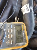
20241010_124516.jpg 3and 2

20241010_124516.jpg2 and 1

20241010_124544.jpg
 
The PCM is on the firewall, passenger side.

On the '96, that 5V Supply shows routing to the ESS, the Throttle Position Sensor (which I don't think you have with the 5-speed), and an EGR Control Module (which was only on the CA models.)

There are three connectors on the PCM, Black (A), White (B), and Gray (C). The pin for the 5V Supply is on the Black connector, Pin #17.

upload_2024-10-10_11-48-44.png
 
The only other 5V Supply from the PCM is on Pin #31 in the Black connector. It goes to the Auto Trans Solenoid Assy which your truck doesn't have. See if you have 5V there. If there's a wire in the connector, it will be an Orange wire.

upload_2024-10-10_12-12-31.png


If you have 5V there, connect it to the Purple/White wire going to the connector for the ESS at the Water Pump and see what you have.
 
Back
Top